Si-c Phase Diagram Sic Phase Diagram
Figure 1 from computer calculations of metastable and stable fe- c-si Figure 1 from phase diagram of silicon from atomistic simulations Si-c phase diagram [25].
Figure 1 from Phase diagram of silicon from atomistic simulations
Phase diagram of the system si – c for pressures above 108 atm. 10 (by (pdf) the ti-si-c system (titanium-silicon-carbon) Titanium silicon carbon
Diagram of phase equilibria of the si-c system.
Figure 9 from the unusual and the expected in the si/c phase diagramChapter 3: bulk growth of silicon carbide Phase diagram of si-c binary system(olesinski & abbaschian, 1996Si-c phase diagram [25]..
Figure 1 from the unusual and the expected in the si/c phase diagramPhase diagram of the ti-si-c system at 1200 @bullet c (after ref. 17 Phase diagram of sic and routes of crystal growth using sublimation orPhase redrawn.

Silicon phase
Figure 2 from the unusual and the expected in the si/c phase diagramCollection of phase diagrams 18: equilibrium phase diagram of the carbon-silicon system [167Calculated si-rich portion of the si-c phase diagram together with.
Sic phase diagram(pdf) the ti-si-c system (titanium-silicon-carbon) Si-c phase diagram (43)Figure 1 from the unusual and the expected in the si/c phase diagram.

Silicon carbide
Figure 4 from the unusual and the expected in the si/c phase diagram[pdf] assessment of the ternary fe–si–b phase diagram (a) pt-si and (b) ti-si binary phase diagrams, and (c) ti-sic ternary[diagram] al si phase diagram.
Sic phase sublimation routesDiagram phase ti calculated 1100 si section re Phase calculation equilibriumThe si-c phase diagram calculated using thermocalc software and the.

Silicon carbon equilibrium
Materials engineering: pengaruh annealing terhadap kekuatan tarik bajaNi–si–c phase diagram at 1,800 k (redrawn from [45]) Iron carbon phase diagram iron graphite phase diagram fundamentalSi-c phase diagram (43).
Figure 2 from the unusual and the expected in the si/c phase diagramPhase binary ti sic ternary annealing contacts sputtered 4h segregation simultaneous ohmic compositions psa Atm pressures permissionIsothermal section of the c-si-ti phase diagram re-calculated at 1100.

System reprinted
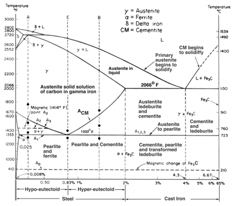
Phase diagram of the ti-si-c system at 1200 @bullet c (after ref. 17Figure 1.1 from properties and characteristics of silicon carbide Fe-c binary isopleth section of the fe-c-si equilibrium phase diagram.
.


